Checking pipe continuity
-
Hello @agroni @Sebastian-Nybäck,
This is interesting,
Do you have any example model to test this?
Is there a relation like this between the ducts?
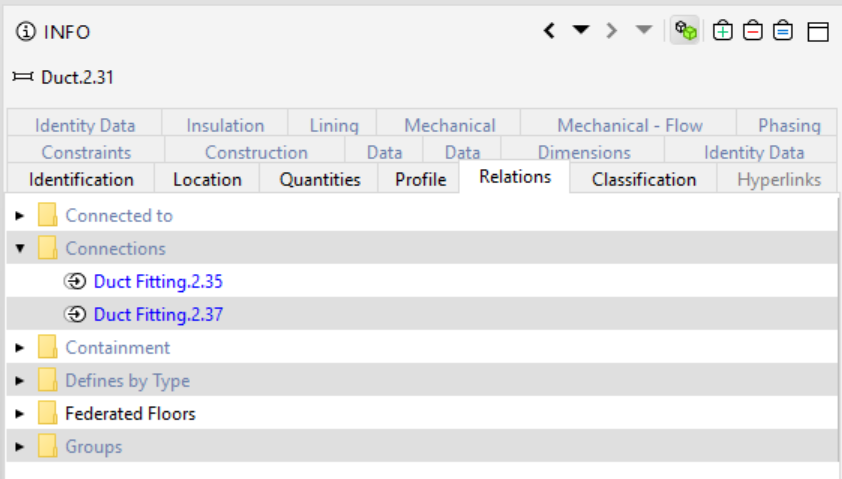
If there is, the rule 231 could be used to check that a duct is connected to at least 2 other components like in this example. Of course you might want to also define the second filter to include only certain type of components which i now have as “any component”.
If there is no relation like this, or the issue is only geometric this gets a bit more tricky and we might need to start by defining vertical and horizontal ducts and then a check accordingly. Would appreciate if you could provide some model that we could test this with and see if it is somehow possible. thanks!
-
@Lauri-Luoma
your suggestion works I believe quite fine. Here are the two pipes, that I have posted in my first comment:
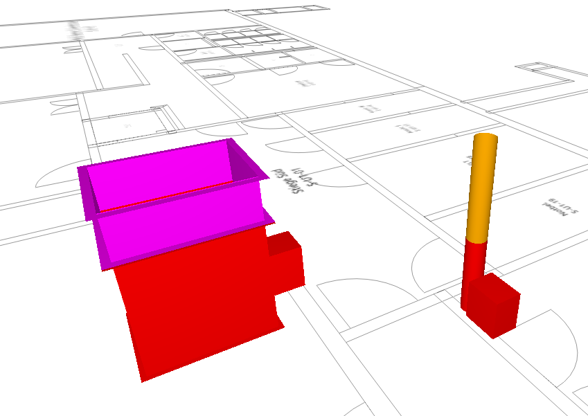
From the results though it is a bit difficult to understand in which direction is the connection missing. Only by turning on the whole HVAC Model shows the deviation.
I was also thinking that it might be good to show the whole lenght of the pipe, but could be also counter productive. In some cases the length of the pipes are enormous which could make the understanding of the result a bit difficult.
btw…the checking has discovered other missing connections on the pipes which I was not able to detect them manually.
thanx for you help…much appreciated. -
Hello, @Lauri-Luoma thank you for your answer and sorry for my late reply. Alas, the two models that I tested in, and where I currently would need to check, did not have the "connections row under Relations. The modeling software is MagiCAD. Is it modeling software specific from where this information comes from? Is there something that the designers needs to “activate” during IFC export? And what other options would be available for this sort of checking?
-
@sebastian-nybäck good question,
I also tested with a IFC model from MagiCAD and it didn’t have the relation. I would advise to contact MagiCAD and ask if there is a setting to export this relation into the ifc file.
Please see the previous message about “in case there is no relation”.
If you have some simple test file with few issues, i’m happy to see if we could create some kind of check with the existing rules. If this is not possible with the existing rules, there is always the API option which allows a creation of a rule from scratch (requires Java developer skills).
-
@Lauri-Luoma Thank you for the reply. In this particular case, all the possible MagiCAD settings and solution has been implemented (as far as I know, although I will double check this). I will inform if there is new information regarding this.
Please see the previous message about “in case there is no relation”.
Yes, I read it, but I am not really sure what this means in practice, could you enlighten me? Due to the nature of the projects, I am unable to provide a test model.
I have come to realize that the Java API is necessary skill to posses, sadly, this something I yet have to learn from scratch, and hopefully I will in the foreseeable future have time to start with it. But for the time being, I have to rely on “conventional” Solibri rules and checking.
-
@sebastian-nybäck Thats great news!
")
Would it be possible for you to share how the export settings should be in MagiCAD to achieve this so anyone struggling with this issue could also learn how to do it.
I assume there are also other checks that the relation between MEP components would allow. Thanks!
-
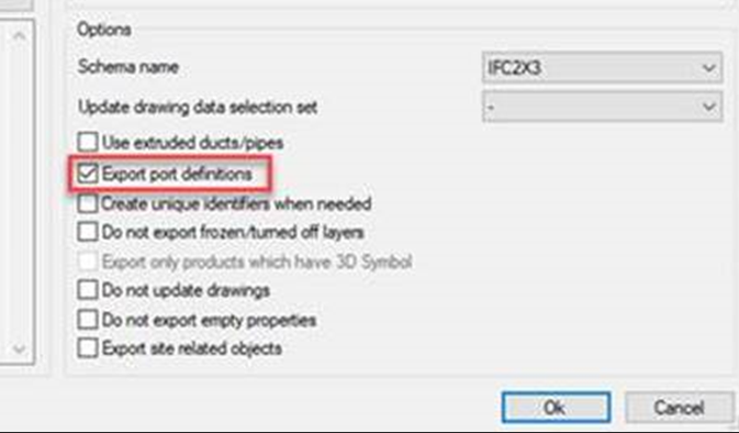
@Lauri-Luoma Of course! The information I recive dfrom MagiCAD, was to have the “Export port definitions” activated in MagiCAD 2021 and with IFC 2x3. With IFC 4, it might be a bit trickier, meaning that it should be included in the export, but it can be that the information can not yet be read by Solibri.
-
 L Lauri Luoma referenced this topic on
Copyright © 2025 Solibri Inc. | Powered by NodeBB